
Our Products
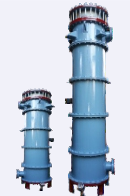
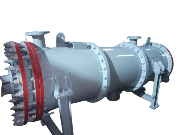
BCAHEX: Graphite Heat Exchanger, Coolers, Condenser, Reboiler, etc.
- The capacity range is HTA from 2 m². to 100 m² available in vertical and horizontal postures.
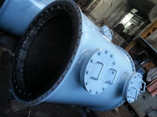
BCAHEX: GRAPHITE BLOCK HEAT EXCHANGERS
- This design is most used by all CPI the world over in the current century. By now It
Advantages :
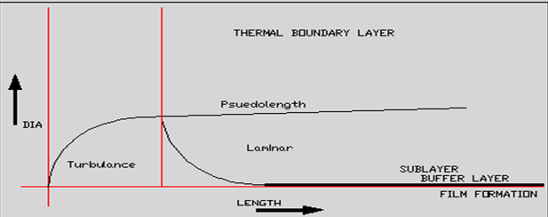
i) L/D Ratio – 200 mm /8 mm
ii) Turbulence – High at even low flow velocities
iii) Scaling – Least due to high turbulence
iv) UD/Fouling Factor – Least
v) Surface Area requirement – Least
vi) Handling – Robust due to solid block support
vii) Maintenance – Easy cleaning of channels.
- Globally, BCPL is the only Corporate Body, manufacturing BCAHEX graphite blocks specifically for Chemical Process Industries. MODELS:

Models :
HTA m 2,
BCAHEX 50 Series 1 m² to 4 m²
BCAHEX 100 Series 2 m² to 15 m²
BCAHEX 100P Series 2 m² to 30 m²
BCAHEX 300P Series 6 m² to 48 m²
BCAHEX 760 Series 50 m² to 100 m²
BCAHEX 900 Series 80 m² to 150 m²
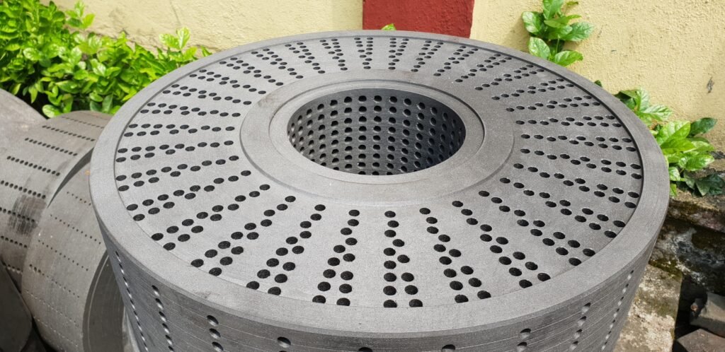
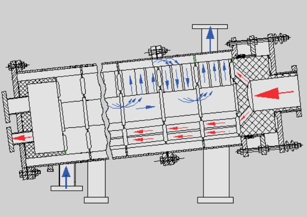
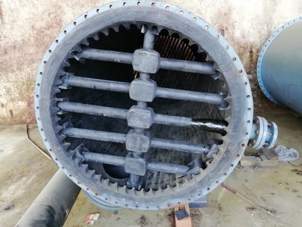
- BCAHEX heat exchanger series is the most advanced 4th Gen design. These are made from impervious graphite blocks with two types of passages Viz.
I) Short converging type radial passages for utility
ii) Small length type axial passages for Process.
iii)Adequate numbers of passes are created on both
sides. It results in very high ‘U’
Thermal Boundary Layer
GRAPHITE HEAT EXCHANGER MODELS :

BCAHEX Dual Utility
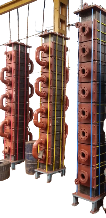
Gen 2nd Cubical Design

GMP Model

Final Hydro Testing Rig
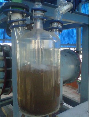
BCARV - Graphite Lined Reactors And Receivers
- BLAST CARBOBLOCKS has Introduced the concept of chemical resistant cum heat conductive lining by transforming graphite into impervious BCARV graphite tiles & graphite cement, very economically since 1982. Excellent corrosion resistance to a wide range of chemicals H₂SO4, Acetic Acid, Xylene, Benzene, Toluene, CCl4, Carbon tiles, bricks, pipes etc
Advantages :
i) Excellent corrosion resistance to a wide range of chemicals.
ii) Good heat transfer from jacket to vessel & vice versa.
iii) Agitator lining is suitable upto 100 rpm.
iv) Ease in maintenance and patch repair of lining is possible.
v) Heating or cooling can be done with ease.
vi)Suitable for full vacuum operation and pressure upto 4 bar.
BCARV Range: 1 KL to 30 KL
& Turnkey Systems
i) Dry HCI Gas Generation System
ii) Acid Regeneration System
iii) HCL Synthesis Unit Spares
iv) Methanol Recovery System
v) Distillation Column
vi) Packed Bed Scrubber System
Vii) Line Pipes & Fittings
Viii) Vacuum Ejector Systems


Larger Phosphoric Acid storage tank lining
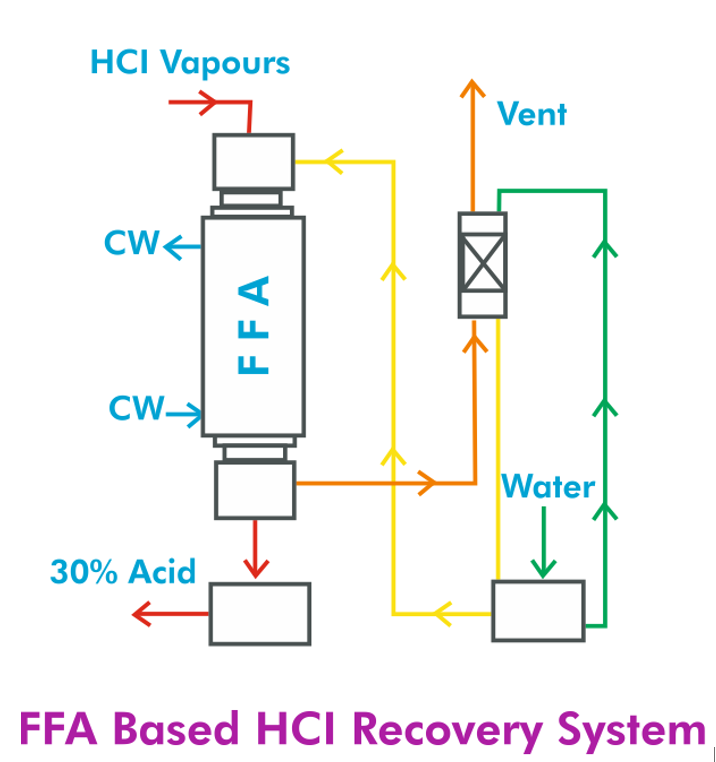
BCAFFA - Falling Film HCI/SO₂ Absorber Systems
- Chemical reactions releasing HCI gas are Common in the chemical process industry. Absorption of HCI gas to make concentrated HCI solution offers dual benefits of meeting "Environmental Protection Standards " and "Value Recovery Benefits". BCAFFA Graphite Falling Film Absorber has a definite advantage over conventional scrubbers. Conventional Scrubbers form adiabatic systems while BCPL design assures an isothermal system.

BCAFFE - Film Evaporator
For many processes and operations, concentrated acid or solution is produced using evaporation techniques. Dilute acid or solution can be concentrated by evaporating excess amount of water from it. For value recovery cum pollution abatement projects the BCAFFE Graphite Falling Film Evaporator is the main work horse. Its special characteristics such as: Compactness, High ‘U’, Non fouling anti-stick surface morphology, and overall cost payback period are very attractive
It is therefore first and foremost choice with the designers of pollution control and effluent treatment systems. The units have been in operation for the concentration of corrosive chemical solutions and acids viz. Sulphuric Acid, Tartaric Acid, Oxalic Acid etc. It also finds application for concentration of solutions prior to crystallization step e.g. recovery of Sulphanillic Acid from spent sulphuric acid solution.
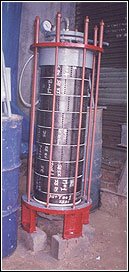
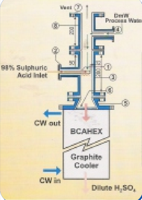
BCADIL - Dilution Unit For Sulphuric Acid
- Dilution Unit Consists of a Primary teflon lined mixing chamber followed by a mixer cum cooler of graphite. The unit is suitable to dilute Sulphuric Acid from 98% to required concentration and cool to desired temp simultaneously
Advantages :
i) High efficiency due to vertical posture.
ii) Continuous outflow of acid is achieved.
iii) very safe for operators and equipment
due to external shell design.
iv) Generation of hot spots is avoided.
v) Very compact floor wise and height wise.
vi) Easy to maintain.

BCACON - Conc. System
Multi-effect concentration systems are designed and developed by BCPL in view of value recovery from spent acid effluent generated in dyestuffs and Pharmaceuticals industries. Under new environmental protection standards disposal of untreated spent acid effluent is prohibited. The lime treatment cost of spent acid is very sizeable. The BCACON system achieves value recovery by concentrating Sulphuric acid up to 70% or more concentration and at the same time treatment cost of effluent is offset by the saleable product recovery to a large extent.
Beside value recovery BCACON system is designed for concentration of other corrosive acids and also for pre crystallization heating.
Application
- Tartaric Acid concentration.
- Oxalic Acid concentration.
- Phosphoric Acid concentration.
- Recovery of Sulphanillic Acid from spent acid solution.

BCAHCL - Recovery System
Construction
The system contains following equipments: BCAFFA Graphite Falling Film Absorber, TGS Graphite tail gas packed bed scrubber.
Similar to BCAHEX heat exchanger, BCAFFA absorber comprises of pile of graphite blocks with headers at both the ends. It differs in basic design from BCAHEX in respect of a distributor block, provided at the top of the BCAFFA. The absorber is followed by a Tail Gas Scrubber. The tail Gas Scrubber is a typical packed bed column in Graphite construction.
Operation
The absorbent liquor is distributed uniformly by the distributor block of the BCAFFA.
The absorbent forms a thin uniform film along the curved wall of holes of the top block, while flowing down to the next block.
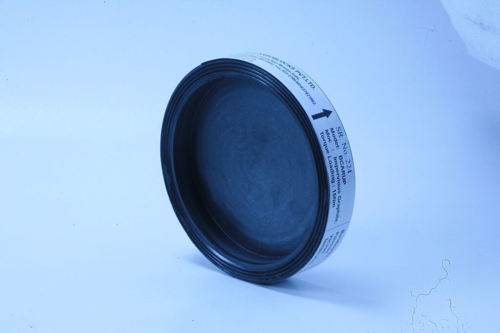
BCARUP - Graphite Rupture Disc
Main Features :
i) BCARUP shows rupture pressure deterioration of one order of magnitude lower than the conventional metallic rupture discs of Nickel etc.
ii) Rupturing pressure reduces only by 10% from room temperature to 150°C.
iii) The rupturing pressure reduces by 9% only in 10,000 hours of exposure to 80% value of rated rupturing pressure.
iv) Pressure range: Normally 1.5 bar to 8 bar. Special Rupture Discs can also be made as per demand/ Design By Party.
v) Rupture area : 70to 80% of nominal size.
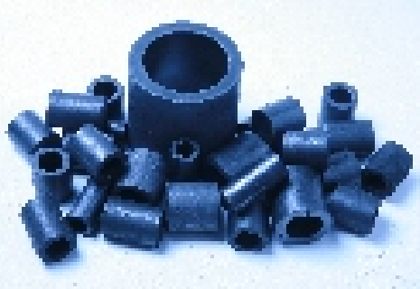
BCADC & BCARR - Graphite Columns And Carbon Raschig Rings
- BCPL offers Graphite columns along with all internal and cylindrical (Raschig) Rings in carbon construction. They offer benefits such as corrosion and thermal-shock resistance as well as high temperature stability.
Main Features :
i) Low coefficient of thermal Expansion.
ii) Light weight and high mechanical strength.
iii) Fully carbonized to eliminated extractableimpurities
iv) Used in most acids, alkalis, solvents at elevated temperature.

BCASC - Bed Scrubber
Introduction
BCASC graphite packed columns are extensively used for absorption of corrosive and hazardous gases. The column is packed with graphite raschig rings. BCASC units are widely used in a number of chemical process industries viz. Pharmaceuticals, Dye Stuffs, Pesticide, Heavy Chemicals, Bulk Drugs, etc.
Construction
A typical BCASC column consists of a cylindrical Impervious Graphite BCARV-A1 shell. There are support plates inside this shell to hold the packing material in position. A liquid distributor provides effective irrigation of the packing. The effective section is packed with graphite raschig rings. Type & size of packing and the height of bed are determined as per loading and flooding characteristics of the scrubbed and scrubbing fluid.
Turnkey Systems
Dry HCL Gas Generation
Introduction
“Energy and Mass can neither be created nor be destroyed, but can be converted from one form to another” The Law of conservation of energy & Mass has always been a motivation to make efficient processes and is the foundation to all our efforts in researches to improve upon existing processes & systems.
Energy conservation and complete utilization with complete mass recovery from input raw materials, eliminating wastages & effluent in any process to provide a “green solution”
has always been a challenge for designers specifically for low value chemicals like liquid hydrochloric acid etc., and is the key to the feasibility of any process for production. The demand for a greener future, to increase efficiency and lower down the pollutant wastages in any process for a better & healthy future leads to inventions to provide better and green solutions in the industry by converting wastages as by-products, which reduces the disposal cost and on the contrary results in value addition in by-products for the company, directly improving finances & company product list. In other words the performance of any chemical plant is judged in the 1st part by its effectiveness to convert a raw material into all possible products & managing critical raw materials in-house to keep up the quality, avoid dependency to meet up the production schedule and making cost competitive products, in the 2nd part by handling the effluent and recovery systems in terms of efficiency and economical feasibility.
In chemical industry/process the limitations become more serious due to economic feasibility of such systems, being a responsible citizen & company we cannot ignore the pollution norms as science and technology is to help us make a better future & not to poison our future, which is a major concern in all industries and leads to minimizing the waste emissions & the ETP treatment load which results in waste handling cost addition.
Dry HCl Gas Generation system is one such example, which resulted in high effluent generation.
The traditional well-known methods successfully implemented are:
1) HCl boiling route.
2) HCl- 98% Supluric acid stripping method.
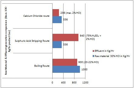
In both the above methods the effluent generation in the process to form product dry HCl gas is very high and handling the effluent or treatment cost is very high. In the 1st process HCl boiling route, dry HCl gas is produced by simple heating in a Re-boiler – packed bed distillation column and condenser-chiller in series in the rectification section as primary gas drying section. In this process bottom product collected is HCl of 20% concentration, as 20 % HCl-water forms an azeotropic mixture, separation of HCl gas and water is not possible in simple distillation.
The following drawbacks were observed in the process.
1.a) HCl recovery in the form of gas from Raw Material 30% Liquid HCl is only 33% of the total HCl present in raw material, i.e. only approx. 1/3rd of the HCl is recovered in the form of gas from raw material.
1.b) Bottom product contains 20% HCl liquid, which mean 2/3rd remains in the bottom product as azeotropic mixture and is wasted, which increases the disposal and effluent handling cost at ETP or treatment cost to very high extent before sending it to ETP.
1.c) Raw material 30% liquid HCl consumption is 10 times of the product gas as only 1/3rd recovery is possible.
1.d) The effluent generated is 900% of the product or 9 times of the product approximately by weight.
1.e) Continuous boiling of the raw material takes place resulting steam consumption is accordingly high with high moisture carry over thereby increasing the condenser load and utility, as it may increase the load of final drying.
1.f) Boiling results in water evaporation as 70% is water in the raw material, which increases the condenser load in the rectification section for moisture removal in gas, as first stage of drying, in case if the efficiency of the condensers drops down or utility availability, the moisture carry over to final drying will be very high and result in high undesirable moisture content in final product.
1.g) Pressure is generated in the system due to boiling method to approximately 1.7-1.8kg/cm2, hence equipment design & safety needs special attention, also high safety-alert systems and precautions leads to high skill labor and overall increasing the equipment and overall operating costs.
1.h) As the system gets pressurized boiling point elevation is also observed.
In the 2nd process 98% sulphuric acid is added to the column directly followed by a cooler and drying section above the column similar to the 1st method. The basis of the process is dilution of sulphuric acid thereby breaking the H-bonding between HCl and water & releasing HCl in the form of gas. 98% sulphuric acid is highly hygroscopic and hence a vigorous dilution takes place from 98% to around 70-65% sulphuric acid, where high heat of dilution is evolved and raising the temperature close to the boiling point of 70-65% acid. The only advantage of this process is approx. 100% HCl conversion in the form of gas from raw material & being an exothermic process, external heating is not required.
The following problems were faced in the process:
2.a) Although the HCl gas conversion is approx. 100% from raw material the requirement of sulphuric acid is approximately 1.5 times of the raw material.
2.b) The effluent generated is 65-70% sulphuric acid as bottom product and is approximately 2-2.25 times by wt of the raw material.
2.c) Addition of 98% sulphuric acid and dilution in the column to release HCl gas, raises the temperature to the boiling point of the liquid i.e. approximately 150-160 ?C.
Equipment design and MOC is also a matter of concern to handle the exotherm on a continuous basis, as even PTFE-lined equipments for sulphuric acid dilution requires high maintenance and prone to break down.
2.d) Effluent requires special MOC for handling, storing and transportation, being highly corrosive or treatment before sending to ETP cost is very high.
2.e) Regeneration of the effluent is not feasible as sulphuric acid concentration above 70% requires special MOC and design to handle vapors forming oleum, temperature and pressure handling equipment, as temperature required for concentration is above 300?C etc.
2.f) Unreleased HCl from 30% HCl raw material is carried over with the bottom product, adding further impurity in the bottom product.
2.g) Maintenance and safety hazards needs special attention as the top and bottom products are highly corrosive & requires skilled labor, increasing the overall equipment and operating cost.
3) Calcium Chloride route:
The challenge to make a system efficient enough to handle the difficulties faced in the above processes lead to innovation of a new process taking Calcium Chloride as a substitute to concentrated sulphuric acid, achieving a “Green Technology Solution” for the process.
Challenge was to find a substitute to sulphuric acid for breaking the azeotrope of HCl-Water at 20% and at the same time the regeneration of the solute to recycle it to the system thereby reducing the effluent discharge & disposal/treatment costs. Calcium chloride being a highly hygroscopic salt is available at a concentration of 28-30% in solution form under atmospheric conditions, it cannot be handled with bare hands in solid state under atmospheric conditions as the dilution of salt is also exothermic, the most essential part was the regeneration possibility of Calcium chloride, exotherm created during dilution of salt & the optimum concentration with quantity required for addition in the column to readily dissolve in water and release HCl gas from the Raw Material 30% HCl to break the azeotrope.
Theoretical study & lab analysis with practical implementation on plant level, confirmed the concentration of 50-55% as the optimum concentration with a boiling point temperature of 130-134?C (varies with different grade and purity) can be feed to the column to start dissolving/absorbing water readily, being highly hygroscopic, as indicated the concentrated Calcium chloride solution under atmospheric conditions readily dissolves in water to give 28-30% solution on wt basis, accordingly the dilution of concentrated calcium chloride in the process can be expected to be around 40% which can be concentrated again to the required and recycled to the system, it is a continuous process with a HCl gas generator & drying section and Calcium chloride regenerator section.
The above block flow-diagram represents the entire green technology process of Dry HCl gas generation & drying system and calcium chloride regeneration system on continuous basis.
The beauty of the system is it separate’s both HCl(in gas form) and water(in liquid form) effectively and with minimum carry over at both ends. Due to lack in optimization of the system on plant level & inexperience in handling the system on plant level the acceptability was low initially, however today in India itself there are 4 plants running successfully with capacities ranging from 25Kg/hr to 100Kg/hr.
Following are the advantages in comparison to other 2 processes described above:
3.a) Conversion of HCl gas from 30% liquid HCl raw material is 100%.
3.b) The effluent generated is maximum 2% HCl as a condensate from calcium chloride regeneration column, which can be easily pretreated by simple caustic dosing before sending to ETP.
3.c) Calcium chloride used is regenerated and recycled to the system on continuous basis in the system.
3.d) As the dehydration is due to salt dilution, pressure is not developed in the system & hence reducing a design parameter.
3.e) As the pressure is not developed, comparatively providing safer operation, reducing leakages and maintenance possibility.
3.f) Overall cost in handling the process, including raw material costs and effluent handling is comparatively very low.
3.g) The chances of moisture carry over under any parameter change or steam fluctuations etc. are comparatively lower, as in boiling route moisture carryover is maximum to the drying section and in sulphuric acid route due to dilution of sulphuric acid the operating temperature rises very close to boiling point of the mixture, which some time may result in carry-over of oleum along with moisture resulting in highly corrosive conditions in vapor form and adding impurity to the product Dry HCl gas.
1st Generation Shell & Tube type was introduced around the year 1900 Limitations…. Gr Tubes & tube sheets are joined by cementing, after some period of thermal cycles cement starts to cracks resulting in leakages. L/D ratio in shell & tube Hx is very high due to long tube length. This develop laminar flow the […]